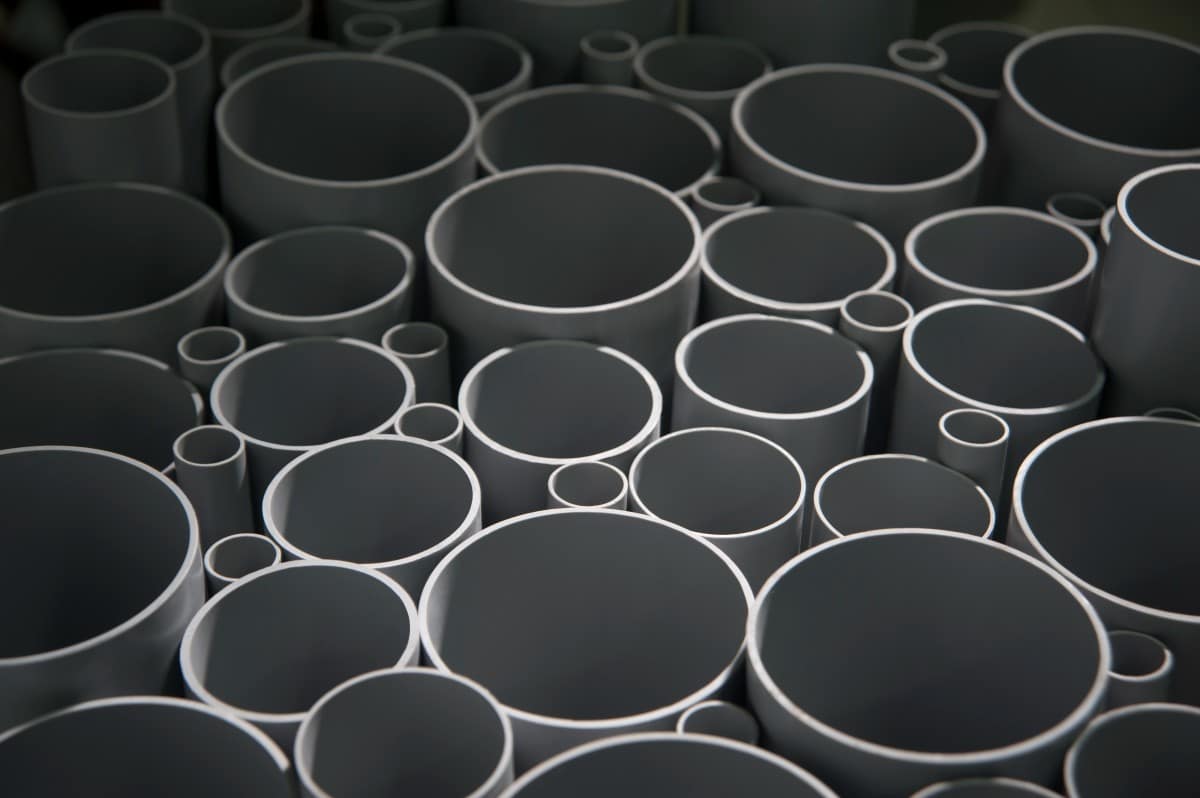

Pipes as per
IS:13592

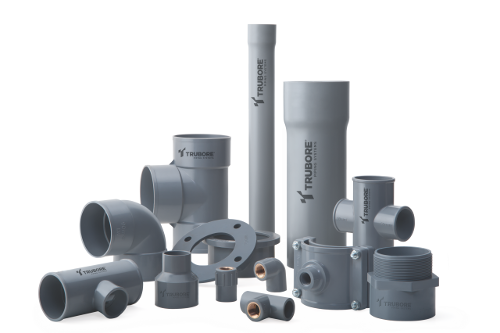
Fitting as per
IS:14735

EXTENSIVELY USED IN

AGRICULTURE
Agricultural Irrigation Pipes and Fittings
AGRICULTURAL PIPING SYSTEM
Trubore offers high-quality Agricultural Piping Systems which have built a strong bond of trust with our customers over the years. They are made of unplasticized polyvinyl chloride (UPVC) material and hence are lead-free, which means that potable water is safely transferred through the system. Moreover, the bore diameter remains constant over the lifetime of the product, guaranteeing a consistent flow of water. Our high-standard products have remained steadfast, upholding the trust bestowed upon us.
APPLICATION
IN AGRICULTURE
- Water supply and distribution schemes.
- Irrigation
OTHERS
- Drinking Water supply and distribution.
- Cable ducting.
- Ventilation pipe line.
- Slurry lines
MAJOR ADVANTAGES
- Light weight, easy to transport, store, handle and install..
- Smooth bore ensures higher flow compared to G.I. pipes & fittings of the same size. No clogging. Saves operational cost.
- Quick to install, solvent cement based jointing system.
- Corrosion resistance – uPVC is rustproof material therefore, bore diamater remains constant, ensuring constant flow over its lifetime.
- Long working life (if operated under normal/recommended conditions).
- Cost-effective. Added value for your money
STANDARDS, QUALITY CONTROL & TESTING
The manufacturing and testing is done for Pipes in accordance with IS: 4985 – 2000.
All the above pipes, except non-pressure pipes are tested for potable water supplies in accordance with their relevant standards and as per the test methods given in IS: 12235.
COEFFICIENT COMPARISON
| Pipe Material | PVC | A.C. | G.I. | C.I. | |
|---|---|---|---|---|---|
| Flow Coefficient | 150 | 130 | 110 | 100 | |
PIPE
| Nominal Outside Diameter (Nominal Size) |
Mean Outside Diameter |
Outside Diameter at any point |
Wall Of Thickness(mm) | Mean Socket Internal Diameter of Mid Point of Socket Length |
||||||||||||||
|---|---|---|---|---|---|---|---|---|---|---|---|---|---|---|---|---|---|---|
| Class 1 0.25 MPa 2.5 Kg/cm² |
Class 2 0.40 MPa 4.0 Kg/cm² |
Class 3 0.60 MPa 6.0 Kg/cm² |
Class 4 0.80 MPa 8.0 Kg/cm² |
Class 5 1.00 MPa 10.0 Kg/cm² |
Class 6 1.25 MPa 12.5 Kg/cm² |
|||||||||||||
| Min | Max | Min | Max | Min | Max | Min | Max | Min | Max | Min | Max | Min | Max | Min | Max | Min | Max | |
| 20 | 20.0 | 20.03 | 19.5 | 20.5 | – | – | – | – | – | – | – | – | 1.1 | 1.5 | 1.4 | 1.8 | 20.1 | 20.3 |
| 25 | 25.0 | 25.0 | 24.5 | 25.5 | – | – | – | – | – | – | 1.2 | 1.6 | 1.4 | 1.8 | 1.7 | 2.1 | 25.1 | 25.3 |
| 32 | 32.0 | 32.3 | 31.5 | 32.5 | – | – | – | – | – | – | 1.5 | 1.9 | 1.8 | 2.2 | 2.2 | 2.7 | 32.1 | 32.3 |
| 40 | 40.0 | 40.3 | 39.5 | 40.5 | – | – | – | – | 1.4 | 1.8 | 1.8 | 2.2 | 2.2 | 2.7 | 2.8 | 3.3 | 40.1 | 40.3 |
| 50 | 50.0 | 50.3 | 49.4 | 50.6 | – | – | – | – | 1.7 | 2.1 | 2.3 | 2.8 | 2.8 | 3.3 | 3.4 | 4.0 | 50.1 | 50.3 |
| 63 | 63.0 | 63.3 | 62.2 | 63.8 | – | – | 1.5 | 1.9 | 2.2 | 2.7 | 2.8 | 3.3 | 3.5 | 4.1 | 4.3 | 5.0 | 63.1 | 63.3 |
| 75 | 75.0 | 75.3 | 74.1 | 75.9 | – | – | 1.8 | 2.2 | 2.6 | 3.1 | 3.4 | 4.0 | 4.2 | 4.9 | 5.1 | 5.9 | 75.1 | 75.3 |
| 90 | 90.0 | 90.3 | 88.9 | 91.1 | 1.3 | 1.7 | 2.1 | 2.6 | 3.1 | 3.7 | 4.0 | 4.6 | 5.0 | 5.7 | 6.1 | 7.1 | 90.1 | 90.3 |
| 110 | 110.0 | 110.4 | 108.6 | 111.4 | 1.6 | 2.0 | 2.5 | 3.0 | 3.7 | 4.3 | 4.9 | 5.6 | 6.1 | 7.1 | 7.5 | 8.7 | 110.1 | 110.4 |
| 125 | 125.0 | 125.4 | 123.5 | 126.5 | 1.8 | 2.2 | 2.9 | 3.4 | 4.3 | 5.0 | 5.6 | 6.4 | 6.9 | 8.0 | 8.5 | 9.8 | 125.1 | 125.4 |
| 140 | 140.0 | 140.5 | 138.3 | 141.7 | 2.0 | 2.4 | 3.2 | 3.8 | 4.8 | 5.5 | 6.3 | 7.3 | 7.7 | 8.9 | 9.5 | 11.0 | 140.2 | 140.5 |
| 160 | 160.0 | 160.5 | 158.0 | 162.0 | 2.3 | 2.8 | 3.7 | 4.3 | 5.4 | 6.2 | 7.2 | 8.3 | 8.8 | 10.2 | 10.9 | 12.6 | 160.2 | 160.5 |
| 180 | 180.0 | 180.6 | 177.8 | 182.2 | 2.6 | 3.1 | 4.2 | 4.9 | 6.1 | 7.1 | 8.0 | 9.2 | 9.9 | 11.4 | 12.2 | 14.1 | 180.2 | 180.5 |
| 200 | 200.0 | 200.6 | 197.6 | 202.4 | 2.9 | 3.4 | 4.6 | 5.3 | 6.8 | 7.9 | 8.9 | 10.3 | 11.0 | 12.7 | 13.6 | 15.7 | 200.3 | 200.6 |
| 225 | 225.0 | 225.7 | 222.3 | 222.7 | 3.3 | 3.9 | 5.2 | 6.0 | 7.6 | 8.8 | 10.0 | 11.5 | 12.4 | 14.3 | 15.3 | 17.6 | 225.3 | 225.7 |
| 250 | 250.0 | 250.8 | 247.0 | 253.0 | 3.6 | 4.2 | 5.7 | 6.5 | 8.5 | 9.8 | 11.2 | 12.9 | 13.8 | 15.9 | 17.0 | 19.6 | 250.4 | 250.8 |
| 280 | 280.0 | 280.9 | 276.6 | 283.4 | 4.1 | 4.8 | 6.4 | 7.4 | 9.5 | 11.0 | 12.5 | 14.4 | 15.4 | 17.8 | 19.0 | 21.9 | 280.4 | 280.9 |
| 315 | 315.0 | 316.0 | 311.2 | 318.8 | 4.6 | 5.3 | 7.2 | 8.3 | 10.7 | 12.4 | 14.0 | 16.1 | 17.3 | 19.9 | 21.4 | 24.7 | 315.4 | 316.0 |
| 355 | 355.0 | 356.1 | 350.7 | 359.3 | 5.1 | 5.9 | 8.1 | 9.4 | 12.0 | 13.8 | 15.8 | 18.2 | 19.6 | 22.6 | 24.1 | 27.8 | 355.4 | 356.0 |
| 400 | 400.0 | 401.2 | 395.2 | 404.8 | 5.8 | 6.7 | 9.1 | 10.5 | 13.5 | 15.6 | 17.8 | 20.5 | 22.0 | 25.3 | 27.2 | 31.3 | 400.4 | 401.0 |
All dimensions are in mm
Note: All pipes are available with ISI Mark except 400mm.
WORKING PRESSURE V/S
TEMPERATURE OF PIPE
As the temperature of the fluid flowing through installation increases, the pressure withstanding capacity of the installation wall decreases. So to find out the pressure rating of PVC Pipes & Fittings at a required temperature, multiply the pressure rating of Pipes & Fittings by derating factor given in the table.
For example: The rated pressure of the installed system is 10Kg.
Up to 25°C, the system can stand 10Kg pressure. If the temperature is 40°C, the derating factor is 0.71. Therefore 10 x 0.71 = 7.1Kg. So, the system can withstand 7.1Kg.
FITTINGS
COUPLER 6KG
Know MoreCOUPLER 10KG
Know MoreCOUPLER LW
Know MoreELBOW 6KG
Know MoreELBOW 10KG
Know MoreELBOW ESTEEM
Know MoreELBOW LW
Know MoreEND CAP 6KG
Know MoreEND CAP 10KG
Know MoreEND CAP LW
Know MoreEND CAP THREADED
Know MoreFAB. BEND 4KG
Know MoreFAB. BEND 6KG
Know MoreFAB. BEND 10KG
Know MoreFAB. COUPLER 4KG
Know MoreFAB. COUPLER 6KG
Know MoreFAB. COUPLER 10KG
Know MoreF.T.A
Know MoreM.T.A
Know MorePVC BALL VALVE
Know MoreREDUCER
Know MoreREDUCING BUSH
Know MoreREDUCING F.T. ADAPTOR
Know MoreREDUCING TEE
Know MoreREDUCING TEE LW
Know MoreTEE 6KG
Know MoreTEE 10KG
Know MoreTEE ESTEEM
Know MoreTEE LW
Know MoreF.T.A BRASS INSERT
Know MoreDO’S & DONT’S
CUTTING
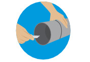

It’s imperative to mark the pipe from all sides so that pipe is cut with the help of a Hand Saw. It should be a right-angle cut from all sides. The cut piece should be with burr on the edges.

Do not cut slant or unevenly.
CHAMFERING
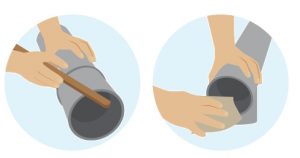
After cutting, the pipe needs to be chamfered from the outer sides. It is advisable to provide approximately 2mm wide, 150 chamfers on the spigot end.
Do not proceed with installation of pipe without chamfering.
DERUBBING AND
RIDGE REMOVAL

Remove all the burr and ridges accumulated on the inner as well as the outer edges of the pipe with the help of deburring Knife, file or abrasive paper.
Do not apply solvent cement without conducting DrDo not proceed with the installation of pipe without deburring.
CLEANING

Thoroughly clean the pipe with a dry cloth where the solvent cement is going to be applied, to avoid dust, dirt, oil, moisture and other foreign material during the installation process.
Do not join the pipe without cleaning the pipe ends.
APPLICATION OF SOLVENT CEMENT

Mark the pipe length to be inserted for jointing. Apply a liberal coat of solvent cement with the help of the
Do not apply excess solvent cement on the pipe and do not use solvent cement by hand.
JOINTING
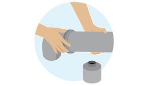
Push the pipe inside the fitting so that it goes inside it equally from all sides. Wipe off excess solvent cement that comes out from all the edges. Hold the joint for 2 minutes so that the jointing is perfect.
Do not use a hammer or half-push the pipe.
FOR THREADED JOINTS
Don’t over-tighten with a pipe wrench.
SPECIFICATIONS
| Fittings | |||
|---|---|---|---|
| Material | Unplasticized Polyvinyl Chloride (uPVC) | ||
| Colour | Dark Grey | ||
| Reference Standards | IS 7834 : 1987 | ||
| Working Temperature of Fluids | Up to 60°C – Continuous, Up to 90°C – Short time, Up to 3 mins. |
||
| Working Pressure (kg/cm²) | 4, 6, 10 & 16 | ||
| End Connections | Solvent sockets, Threads (For transition fittings) | ||
HAZEN – WILLIAM’S FLOW
| Pipe Material | PVC | A.C. | G.I. | C.I. | |
|---|---|---|---|---|---|
| Flow Coefficient | 150 | 130 | 110 | 100 | |
PROPERTIES OF
UPVC PIPES
| Mechanical | |||
|---|---|---|---|
| Tensile Strength | 415 – 525 kg/cm² | ||
| Compression Strength | 550 – 910 kg/cm² | ||
| Flexural Strength | 680 – 1100 kg/cm² | ||
| Izod Impact Strength | 4 – 5 kg/cm² | ||
| Shore Hardness | D 65 – 85 |
| THERMAL | |||
|---|---|---|---|
| Coefficient of Linear Expansion | 0.08 mm/M°C | ||
| Vicat Softening Temperature | > 78°C | ||
| Max. Operating Temperature | 60°C |
| Physical | |||
|---|---|---|---|
| Water Absorption | < 4mg/cm³ |

