


Pipes as per
IS:12818

EXTENSIVELY USED IN
-

AGRICULTURE
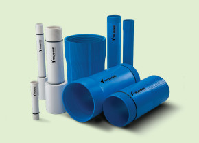
Borewell Casing Pipes
Trubore borewell pipes are manufactured with the bore diameter remaining constant over the lifetime of the system, guaranteeing a consistent flow of water. Trubore’s Borewell Piping systems consist of Column Pipes/ Submersible pipes, Ribbed Screen Pipes and Casing Pipes which are essential for groundwater extraction. Furthermore, to provide a seamless functioning product, Trubore has included an innovative circlip lock into the column pipe which strengthens the bond of the pipe with the coupler which is why we say fit it and forget it.
APPLICATIONS
- Borewell pipes are used to extract ground water for farms and fields.
- For connections to residential & commercial buildings, public places etc.
MAJOR ADVANTAGES
- Easy to transport, store, handle and install.
- Bore diameter remains constant, ensuring constant.
- Saves labour & installation cost.flow over lifetime
- Drinking Water supply and distribution.
- Smooth bore ensures higher flow compared to G.I. pipeline.
- Superior resistance to most of the chemicals, no scaling, of the same size. No clogging. makes the system almost maintenance free.
- Long life.
BOREWELL PIPES SPECIFICATIONS
| Specifications | Screen Pipes | Casing Pipes | Submersilbe Delivery Pipes/ Rising Main Pipes |
||||||
|---|---|---|---|---|---|---|---|---|---|
| Ribbed | Plain | Medium | CM | CS | CD | ||||
| Color | Blue | Blue | Blue | Blue | Blue | Blue | Ivory | ||
| Standard Length | 3m | 3m | 3m | 3m | 3m | 3m | 3m | ||
| Standards | IS – 12818-2010 / Marked items will bear ISI marks | ||||||||
| Type of threads | 11 TPI V threads upto 80mm, 100mm (CS) Casing pipes as per IS-554-1999 & Trapezoidal threads form 100mm as per IS-12818-2010 with rubber sealing rings. |
Square | |||||||
| Notes: | |||||||||
| A) Suitability: For wells | Above 80m 262ft upto 250m 820ft |
upto 80m 262 ft. | Above 250m 820ft.
upto 450m |
||||||
| B) Threads | Borewell casing Pipes will have internal threads at one end external threads at other end with thread protection cover. | ||||||||
| C) Specification required | Slot width 0.75, 1.00, 1.50, 2.00 & 3.00 mm. | ||||||||
DIMENSIONS
MEDIUM WELL SCREEN (RMS) & DEEP WELL SCREEN (RDS) PIPES WITH RIBS/RIBBED SCREEN PIPES.
| Medium Well Screen(RMS) | Deep Well Screen(RDS) | ||||||||||
|---|---|---|---|---|---|---|---|---|---|---|---|
| Nominal Diameter (DN) |
Mean Outer Diameter of pipe (d) (mm) |
Mean Outer Diameter over Connection, (d’s’) |
Wall Thickness ‘e’ (under ribs) (mm) |
Mean Outer Diameter over Connection, (d’s’) |
Wall Thickness, ’e’ (mm) |
||||||
| Inches | mm | Min | Max | Max | Min | Max | Max | Min | Max | ||
| 1 1/2 | 40.0 | 52.00 | 52.20 | 56.00 | 3.50 | 4.00 | – | – | – | ||
| 2 | 50.0 | 64.00 | 64.20 | 69.00 | 4.00 | 4.60 | – | – | – | ||
| 3 | 80.0 | 92.00 | 92.30 | 98.00 | 4.00 | 4.60 | – | – | – | ||
| 4 | 100.0 | 117.00 | 117.30 | 124.00 | 5.00 | 5.70 | 129.00 | 7.00 | 7.90 | ||
| 4 1/2 | 115.0 | 129.00 | 129.30 | – | – | – | 141.00 | 7.50 | 8.50 | ||
| 5 | 125.0 | 144.00 | 144.40 | 154.00 | 6.50 | 7.30 | 156.00 | 8.00 | 9.00 | ||
| 6 | 150.0 | 169.00 | 169.40 | 182.00 | 7.50 | 8.50 | 184.00 | 9.50 | 10.70 | ||
| 7 | 175.0 | 204.00 | 204.50 | 219.00 | 8.80 | 9.80 | 221.00 | 11.80 | 13.60 | ||
| 8 | 200.0 | 229.00 | 229.50 | 247.00 | 10.00 | 11.20 | 251.00 | 13.00 | 14.80 | ||
| 10 | 250.0 | 284.00 | 284.50 | 302.00 | 12.50 | 14.00 | 309.00 | 16.00 | 17.60 | ||
| 12 | 300.0 | 334.00 | 334.60 | 356.00 | 14.50 | 16.20 | 363.00 | 19.00 | 21.00 | ||
| 14 | 350.0 | 404.00 | 404.70 | 432.00 | 17.50 | 19.50 | 437.00 | 21.50 | 23.90 | ||
| 16 | 400.0 | 454.00 | 454.80 | 483.00 | 19.50 | 21.70 | 494.00 | 23.50 | 26.10 | ||
PLAIN WELL SCREEN (PMS) & PLAIN DEEP WELL SCREEN (PDS) PIPES
| Plain Medium Well Screen(PMS) | Plain Deep Well Screen(PDS) | ||||||||||||
|---|---|---|---|---|---|---|---|---|---|---|---|---|---|
| Nominal Diameter (DN) |
Mean Outer Diameter of pipe (d) (mm) |
Mean Outer Diameter over Connection, (d’s’) |
Wall Thickness (e) (mm) |
Outer Diameter at any point d’e’ (mm) |
Mean Outer Diameter over Connection, (d’s’) |
Wall Thickness, ’e’ (mm) |
|||||||
| Inches | mm | Min | Max | Max | Min | Max | Min | Max | Max | Min | Max | ||
| 8 | 200 | 225.00 | 225.50 | 243.00 | 10.00 | 11.20 | 224.50 | 225.80 | 247.00 | 13.00 | 14.80 | ||
| 10 | 250 | 280.00 | 280.50 | 298.00 | 12.50 | 14.00 | 279.40 | 280.80 | 304.00 | 16.00 | 17.60 | ||
| 12 | 300 | 330.00 | 330.60 | 352.00 | 14.50 | 16.20 | 329.30 | 331.00 | 359.00 | 19.00 | 21.00 | ||
| 14 | 350 | 400.00 | 400.70 | 428.00 | 17.50 | 19.50 | 399.20 | 401.20 | 433.00 | 21.50 | 23.90 | ||
| 16 | 400 | 450.00 | 450.80 | 479.00 | 19.50 | 21.70 | 449.10 | 451.30 | 490.00 | 23.50 | 26.10 | ||
MEDIUM WELL CASING PIPES (CM) & SHALLOW WELL CASING (CS) PIPES.
| Medium Well Casing (CM) Pipes | Shallow Well Casing (CS) Pipes | ||||||||||
|---|---|---|---|---|---|---|---|---|---|---|---|
| Nominal Diameter (DN) |
Mean Outer Diameter of pipe (d) (mm) |
Mean Outer Diameter over Connection, (d’s’) |
Wall Thickness ‘e’ (mm) |
Mean Outer Diameter over Connection, (d’s’) |
Wall Thickness, ’e’ (mm) |
||||||
| Inches | mm | Min | Max | Max | Min | Max | Max | Min | Max | ||
| 1 1/2 | 40.0 | 48.00 | 48.20 | 52.00 | 3.50 | 4.00 | – | – | – | ||
| 2 | 50.0 | 60.00 | 60.20 | 65.00 | 4.00 | 4.60 | – | – | – | ||
| 3 | 80.0 | 88.00 | 88.30 | 94.00 | 4.00 | 4.60 | – | – | – | ||
| 4 | 100.0 | 113.00 | 113.30 | 120.00 | 5.00 | 5.70 | – | – | – | ||
| 5 | 125.0 | 140.00 | 140.40 | 150.00 | 6.50 | 7.30 | – | – | – | ||
| 6 | 150.0 | 165.00 | 165.40 | 178.00 | 7.50 | 8.50 | 174.00 | 5.70 | 6.50 | ||
| 7 | 175.0 | 200.00 | 200.50 | 215.00 | 8.80 | 9.80 | 211.00 | 7.00 | 7.80 | ||
| 8 | 200.0 | 225.00 | 225.50 | 243.00 | 10.00 | 11.20 | 238.00 | 7.60 | 8.80 | ||
| 10 | 250.0 | 280.00 | 280.50 | 298.00 | 12.50 | 14.00 | 292.00 | 9.60 | 11.00 | ||
| 12 | 300.0 | 330.00 | 330.60 | 352.00 | 14.50 | 16.20 | – | – | – | ||
DEEP WELL CASING PIPES (CD)
| Nominal Diameter (DN) |
Mean Outer Diameter of pipe d’em’ (mm) |
Outer Diameter at any point d’e’ (mm) |
Mean outer Diameter over Connection, (d’s’) |
Wall thickness, ‘e’ (mm) |
|||||||||||||||
|---|---|---|---|---|---|---|---|---|---|---|---|---|---|---|---|---|---|---|---|
| Inches | mm | Min | Max | Min | Max | Max | Min | Max | |||||||||||
| 4 | 100.0 | 113.00 | 113.30 | 112.80 | 113.40 | 125.00 | 7.00 | 7.90 | |||||||||||
| 4 1/2 | 115.0 | 125.00 | 125.30 | 124.90 | 125.40 | 137.00 | 7.50 | 8.50 | |||||||||||
| 5 | 125.0 | 140.00 | 140.40 | 139.70 | 140.50 | 152.00 | 8.00 | 9.00 | |||||||||||
| 6 | 150.0 | 165.00 | 165.40 | 164.60 | 165.60 | 180.00 | 9.50 | 10.70 | |||||||||||
| 7 | 175.0 | 200.00 | 200.50 | 199.60 | 200.60 | 217.00 | 11.80 | 13.60 | |||||||||||
| 8 | 200.0 | 225.00 | 225.50 | 224.50 | 225.80 | 247.00 | 13.00 | 14.80 | |||||||||||
| 10 | 250.0 | 280.00 | 280.50 | 279.40 | 280.80 | 304.00 | 16.00 | 17.60 | |||||||||||
| 12 | 300.0 | 330.00 | 330.60 | 329.30 | 331.00 | 359.00 | 19.00 | 21.00 | |||||||||||
| 14 | 350.0 | 400.00 | 400.70 | 399.20 | 401.20 | 433.00 | 21.50 | 23.90 | |||||||||||
| 16 | 400.0 | 450.00 | 450.80 | 449.10 | 451.30 | 490.00 | 23.50 | 26.10 | |||||||||||
SUBMERSIBLE DELIVERY PIPES/RISING MAIN PIPES
| Product OD-Outside Dia. ND-Nominal Dia. In mm |
Pressure Kg/cm² |
Safe total pump delivery Head(m) |
Ultimate Breaking Load (Kg) |
Safe Pulling Load (Kg) |
Screen Colour |
STD Packing |
||
|---|---|---|---|---|---|---|---|---|
| Size | Type | Category | ||||||
| 1″ OD-33.30 ND-25.00 | Coupler | V 4 | 12.5 | 125 | 850 | 500 | Royal Claret | 28 |
| 17 | 170 | 950 | 600 | Green | ||||
| Medium | 22 | 220 | 1250 | 750 | Orange | 28 | ||
| Std | 38 | 380 | 1750 | 1100 | Red | 28 | ||
| Bell Form Coupler | V 4 | 12.5 | 125 | 850 | 500 | Royal Claret | 28 | |
| 17 | 170 | 950 | 600 | Green | ||||
| 1 1/4″ OD-42.10 ND-32.00 | Coupler | V 4 | 12.5 | 125 | 1350 | 800 | Royal Claret | 20 |
| 17 | 170 | 1500 | 900 | Green | ||||
| Medium | 21 | 210 | 1725 | 1000 | Orange | 20 | ||
| Std | 30 | 300 | 2350 | 1400 | Red | 20 | ||
| Heavy | 39 | 390 | 2900 | 1750 | Blue | 20 | ||
| Bell Form Coupler | V 4 | 12.5 | 125 | 1350 | 800 | Royal Claret | 20 | |
| 17 | 170 | 1500 | 900 | Green | ||||
| 1 1/2″ OD-48.20 ND-40.00 | Coupler | V 4 | 16 | 160 | 1850 | 1100 | Green | 16 |
| Medium | 22 | 220 | 2400 | 1450 | Orange | 16 | ||
| Std | 26 | 260 | 2750 | 1650 | Red | 16 | ||
| Heavy | 39 | 390 | 3700 | 2250 | Blue | 16 | ||
| 2″ OD-60.20 ND-50.00 | Coupler | Medium | 14 | 140 | 2450 | 1450 | Orange | 12 |
| Std | 20 | 200 | 3500 | 2100 | Red | 12 | ||
| Heavy | 27 | 270 | 4600 | 2800 | Blue | 12 | ||
| 2 1/2″ OD-75.00 ND-65.00 | Coupler | Medium | 11 | 110 | 3100 | 1800 | Orange | 8 |
| Std | 16 | 160 | 4500 | 2700 | Red | 8 | ||
| Heavy | 26 | 260 | 6450 | 3900 | Blue | 8 | ||
| 3″ OD-88.00 ND-80.00 | Coupler | Medium | 11 | 110 | 4100 | 2450 | Orange | 6 |
| Std | 17 | 170 | 6400 | 3800 | Red | 6 | ||
| Heavy | 26 | 260 | 8900 | 5300 | Blue | 6 | ||
| 4″ OD-113.00 ND-100.00 | Coupler | Medium | 10 | 100 | 6500 | 3900 | Orange | 4 |
| Std | 15 | 150 | 9250 | 5550 | Red | 4 | ||
| Heavy | 26 | 260 | 14450 | 8700 | Blue | 4 | ||
DO’S & DONT’S
JOINTING & INSTALLATION.

- Ensure that pipes threads are proper and clean it with normal water to avoid forceful jointing.
- Ensure that rubber seal is properly sealed in its position, without any twist/cut while tightning the threads to avoid leakages.
- Before jointing the pipes with pump, it is recommended to provide pump guard between pipe coupler and pipe metal adapater.
- Assemble the TRUBORE G I metal adapter with pump.
- During assembly of the pipe.,initially hold the pipe coupler with hands & tighten it, for final jerk always use rope strap wrench to tighten the pipe properly.
- Fix a nylon rope to cast iron adapter as a safety measure against failing of submersible pump due to mishape.
- Clamp the pipe below coupler (at defined location at pipe) at the time of lowering Trubore rising main pipe into the borewell.
- Always use chain pulley for lowering Trubore rising main pipe.


- Don’t use any chemical for cleaning the pipe thread.
- Don’t apply lubricant on borewell casing pipe thread.
- Don’t over-tighten the joints to avoid breakages.

- Don’t use pipe/chain wrench to tighten the joints.
- Don’t dump gravel at a very high rate to avoid excess abrasion.
- Don’t use any chemical for cleaning the pipe thread.
- Don’t use agri-pipes(with solvent cement joint) for borewells, as their mechanical strength is not designed for this application.
- Don’t hammer the pipes during assembly.
HANDLING, TRANSPORTATION & STORAGE.
- Pipes shall be stored in shade on resonably flat surfaces, free from sharp objects.

- Don’t hammer the pipes during assembly.
- Don’t dump the pipes over each other.
- Don’t remove the packing & thread protection covers of borewell pipes till the time of installation.
- Don’t drag/throw the pipes during handling to avoid thread damages.
GUIDELINES FOR INSTALLATION
OF SCREEN & CASING PIPE.
- Drill the bore of the required size & depth in the gorund using the method of auger drilling/water jet boring/hydraulic rotart drilling/core drilling. During drilling, care should be taken that it is vertically straight down without any bends.
- To contstruct the bore/tube well, CASING/SCREENING & RISING MAIN pipes are required.
- CASING pipes are highly recommended in the area where loose soil & slit/loose boulders & loose stones are prevalent.
- Fit the rubber gasket properly on the space provided on the ribbed screen/casing pipes.
- Fit C damp below the bell end on the pipe and lower the assembly done with the help of chain pulley block (Provide sand trap with endplug as necessary).
- Ater lowering the pipe up to the clamp level, fix the rubber gasket on another pipe & tighten it gently with the lowered pipe. After tightening, use pipe/chain wrench for proper jointing, but do not over tighten.
- Fix the next clamp with the pipe above and bend below and connect the chain pulley with clamp.
- Remove the clamp of lowered pipe & start lowering further.
- Repeat the jointing method till the required depth of borewell.
- Centering guide to be fitted wherever necessary.
- Fill the gravel between pipe & bore hole.
GUIDELINES FOR INSTALLATION
OF RISING MAIN PIPE.
- Once screen & casing pipes are installed properly, follow the below guidelines for installation of PUMP & SUBMERSIBLE DELIVERY PIPE.
- Before starting installation, pre-check if submersible pump is in good working condition.
- Join the Trubore metal adapter with the submersible pump with the help of chain wrench
- Before starting the pipe assembly, clean the pipe threads with normal water to avoid forceful jointing.
- Before joining the pipe with pump, ensure the pump guard is installed properly between pipe coupler & pump metal adapter.
- Assemble SUBMERSIBLE DELIVERY PIPE with pump, always use strap wrench/rope for last jerk.
- Fix a nylon rope to cast iron adapter as a safety measure against falling of submersible pump due to mishap (run the nylon rope throughout the borewell length & tie it with top clamp).
- Fit the C clamp below coupler(at defined location on pipe) & lower the assembly inside the CASING pipe carefully with the help of a chain pulley.
- Once casing pipe will be lowered in the borewell up to the clamp level, fix the rubber ring on the other pipe & tighten it gently with the help of rope/strap wrench, till half of the ring gets inside the coupler.