


Pipes
Schedule 40,80 –
As per ASTM D – 1785(Plain Ended)
Fittings
Schedule 80 as per ASTM D – 2467 Schedule 40 as per ASTM D – 2466
EXTENSIVELY USED IN

Commerical
Swimming pools

RESIDENTIAL

Industry
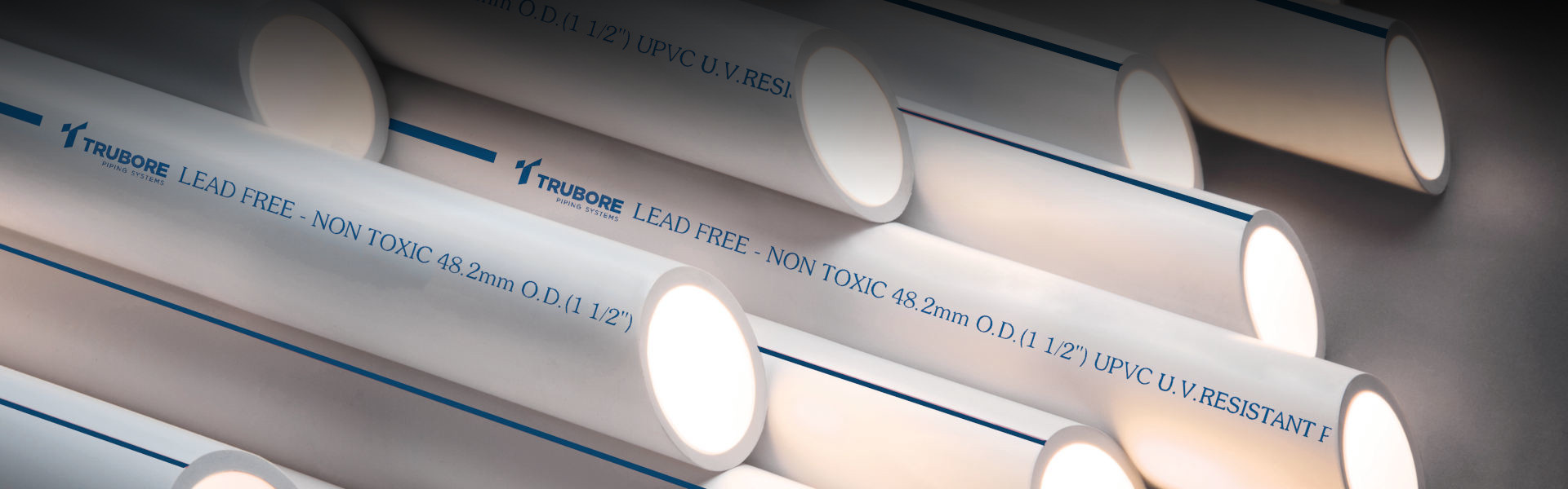
uPVC Plumbing System
uPVC pipes & fittings are made of unplasticized polyvinyl chloride material. This piping system can withstand temperatures up to 600C and is only used for cold water applications. This system is extensively used in commercial, residential & industries for the usage of cold water. These pipes and fittings are joined with the help of uPVC solvent cement. With the use of solvent cement, the joints become everlasting once installed. Threaded joints are also provided for transition joints. The pipes are manufactured in a variety of sizes and thicknesses to suit the usage requirement.
APPLICATIONS
- uPVC pipes and fittings manufacturers in india, Indoor and Outdoor use for cold water applications
- Residential complexes, commercial buildings, public utilities, swimming pools
- RO and DM water plants
- For Concealed, down take & terrace looping
MAJOR ADVANTAGES
- Lead-free material ensures safe drinking water.
- Exceptional corrosion resistance ensures constant flow over its lifetime.
- Light-weight but strong.
- Self-extinguishing(Does not support combustion).
- uPVC pipes have High impact resistance, ensures high impact quality performance at lower temperatures.
- Fast and Easy Installation.
- Long Life.
PIPE DIMENSIONS
| Pressure for pipes (Solvent Weld) at 23℃ | ||||||
|---|---|---|---|---|---|---|
| Scheduled 40 | Scheduled 80 | |||||
| Nominal Bore | Outside Diameter | Wall thickness | Working Pressure | Wall thickness | Working Pressure | |
| (mm) | (inch) | (mm) | (mm) | Kg/cm2 | (mm) | Kg/cm2 |
| 15 | 1/2 | 21.34 ±0.10 | 2.77 + 0.51 | 42.20 | 3.73 + 0.51 | 59.75 |
| 20 | 3/4 | 26.67 ±0.10 | 2.87 + 0.51 | 33.75 | 3.91 + 0.51 | 48.50 |
| 25 | 1 | 33.40 ±0.13 | 3.38 + 0.51 | 31.60 | 4.55 + 0.53 | 44.25 |
| 32 | 1 1/4 | 42.16 ±0.13 | 3.56 + 0.51 | 26.00 | 4.85 + 0.58 | 36.60 |
| 40 | 1 1/2 | 48.26 ±0.15 | 3.68 + 0.51 | 23.25 | 5.08 + 0.61 | 33.00 |
| 50 | 2 | 60.32 ±0.15 | 3.91 + 0.51 | 19.65 | 5.54 + 0.66 | 28.10 |
| 65 | 2 1/2 | 73.02 ±0.18 | 5.16 + 0.61 | 21.10 | 7.01 + 0.84 | 29.55 |
| 80 | 3 | 88.90 ±0.20 | 5.49 + 0.66 | 18.25 | 7.62 + 0.91 | 26.00 |
| 100 | 4 | 114.30 ±0.23 | 6.02 + 0.71 | 15.50 | 8.56 + 1.02 | 22.50 |
| 150 | 6 | 168.28 ±0.28 | 7.11 + 0.86 | 12.60 | 10.97 + 1.32 | 19.65 |
| 200 | 8 | 219.30 ±0.38 | 8.18 + 0.99 | 11.20 | 12.70 + 1.52 | 17.50 |
| 250 | 10 | 273 ±0.38 | 9.27 + 1.12 | 9.90 | 15.06 + 1.80 | 16.20 |
Note :
1. For threaded pipes and fittings, the working pressure at 23℃ shall be considered as 50% rating.
2. Pressure rating at uPVC pipes and fittings is tempreture related. Derating factor shall be applied for applications at higher.
| Working Pressure for Fittings (Solvent Weld) at 23℃ | |||
|---|---|---|---|
| Scheduled 40 | Scheduled 80 | ||
| Nominal Bore | Working Pressure | ||
| (mm) | (inch) | Kg/cm2 | Kg/cm2 |
| 15 | 1/2 | 25.30 | 35.85 |
| 20 | 3/4 | 20.25 | 29.10 |
| 25 | 1 | 18.95 | 26.55 |
| 32 | 1 1/4 | 15.60 | 21.95 |
| 40 | 1 1/2 | 13.95 | 19.80 |
| Working Pressure for Fittings (Solvent Weld) at 23℃ | |||
|---|---|---|---|
| Scheduled 40 | Scheduled 80 | ||
| Nominal Bore | Working Pressure | ||
| (mm) | (inch) | Kg/cm2 | Kg/cm2 |
| 50 | 2 | 11.75 | 16.85 |
| 65 | 2 1/2 | – | 17.70 |
| 80 | 3 | – | 15.60 |
| 100 | 4 | – | 13.50 |
| 150 | 6 | 7.50 | – |
Note: Working pressure for metal insert fittings is 15Kg/cm2
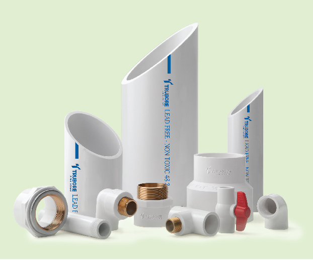
UPVC FITTINGS
BALL VALVE
Know MoreBLIND FLANGE
Know MoreCOUPLER
Know MoreCROSS OVER BEND
Know MoreELBOW
Know MoreELBOW 45°
Know MoreEND CAP
Know MoreEQUAL TEE
Know MoreF.T.A
Know MoreFOUR WAY TEE
Know MoreM.T.A
Know MoreOPEN FLANGE
Know MoreREDUCER
Know MoreREDUCING BUSH
Know MoreREDUCING TEE
Know MoreTANK CONNECTOR MOULDED
Know MoreUNION
Know MoreF.T.A (BRASS)
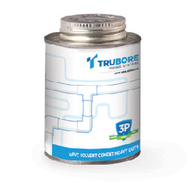
Know MoreSOLVENTS
DO’S & DONT’S
DESIGN STAGE

- Consider provision for expansion and contraction of piping installation
- Consider pressure de-rating factor for use of upvc pipe line at higher temperature for a maximum of up to 45℃.
HANDLING, TRANSPOTATION & STORAGE
- UPVC Pipes and fittings shall be stored in covered area.
- Pipes shall be stored on levelled flat forund.
- The shacking height of a upvc pipe stack shall not be more than 50 meters

- Do not drag or drop/throw pipes while loading/unloading & shifting.
- Do not overhang the pipes out of vehicle body while transporting.
- Don not stack the pipes for more than 1.5 meters of height.
JOINTING & INSTALLATION
- In case of threads to be done in pipes,parallel threads are recommended.
- Use only uPVC Solvent cement for jointing. Other types of solvent cements may contain ingredients which are not recommended.
- Cut the pipe at right angle to its axis.
- Before making joint,remove burr and clean the pipe surface/threads.
- For Solvent cement joints rotate the pipe through the quator turn while inserting in the upvc fitting.
- Clean excess solvent cement which comes out from joint.
- Cure the solvent joint for 24 hours for atleast 24 hours in dry weather & 48 hours in humid weather.
- For threaded joint,use teflon tape for thread smiling.
- Use recommened spacing for clamping the installation.
- In Case of concealed pipeline, plastoring with 1:4 mortar is recommended
- Do not use Solvent cement whick is gelled/not free flowing.
- While solvent cementing avoid heat exposure or open flame.
- Do not hammer the pipeline.
- Do not over-tighten the treaded joints.
TESTING & COMMISSIONING
- Pressure test the installation with water only.
- Before testing, ensure that all joints are cured fully.
- Ensure that all waves are air relief mechanism at the end of elevations are opened.
- During initial filling of pipeline,limit water velocity up to 0.3m/s for releasing the entrapped air.
- Continue fillig until entrapped air is completely removed from installation
- Do not use air or gas for installation testing.